
Buying Guides
CNC spindle selection is decided by a curve, not by a single number. A spindle has a rated power and a maximum speed, but what it actually delivers is described by its torque-speed curve: constant torque up to a base speed, constant power above it, and a rapid fall in torque at the top of the range. Two spindles with identical rated power can behave completely differently at the low speed where you take a heavy cut on a large diameter. Match the curve to the workpiece — material, diameter, depth of cut and the speed the tool needs — and the rest of the specification follows.
The curve is the specification that matters
A spindle drive has two physical limits. Below a certain speed it is limited by how much torque the motor and its drive can produce, which is broadly constant across that range. Above it the drive can no longer hold that torque at the increasing speed, so power becomes the limit instead and torque falls away in inverse proportion to speed. The point where the two regimes meet is the base speed, and the shape of the whole curve is what a machine tool builder means by “the spindle curve”.
This is why comparing spindles by rated power alone misleads. A spindle rated at a high power with a small constant-torque region is a finishing spindle: it will take light cuts at high speed and be comfortable there. A spindle with a lower rated power but a large constant-torque region is a roughing spindle: it will take a heavy interrupted cut at low speed without stalling. Both statements are true and neither is visible in the rated power figure. When you ask a builder for spindle data, ask for the torque-speed curve and the base speed, not just the kilowatts.
The second thing to read off the curve is where your work actually sits, and it is the step most often skipped in cnc spindle selection. Most of a machine’s life is spent in a narrow band of speeds determined by the workpiece diameter and the cutting speed the material wants. If that band falls in the falling-torque region, the machine will perform well below its advertised capability on your parts — and no amount of power will compensate, because torque, not power, is what breaks a chip at low speed.
One question to ask before any spindle comparison
“What is the spindle torque at the speed my part will actually run at?” If the answer is a single rated figure with no speed attached to it, the comparison cannot be made. Torque without a speed is not a specification.
Four spindle architectures and where each fits
The architecture decides which part of the curve the spindle is good at, and how much of the drive’s output reaches the tool. It is the first decision in cnc spindle selection, because it cannot be changed later.
| Architecture | How it behaves | Strengths | Where it fits |
|---|---|---|---|
| Belt-driven | The motor sits outside the headstock and drives the spindle through a belt and pulley step | Simple, easy to maintain, isolates motor heat from the spindle, and can be re-geared | General turning where a wide speed range matters more than the very top speed |
| Direct-coupled | The motor shaft is coupled to the spindle without a belt | Fewer wearing parts, better transmission at high speed, no belt slip | Higher speed turning and applications where belt replacement is unwanted downtime |
| Two-step or gear range | Two mechanical ranges multiply the available torque at low speed | The largest low-speed torque for heavy roughing on big diameters | Large-diameter, heavy-cut work where the top speed will not be used |
| Integrated motorised spindle | The rotor is built onto the spindle shaft itself | Highest speeds and the quickest dynamic response, short length, no transmission losses | Small-diameter, high-speed work and machining centres where speed defines productivity |
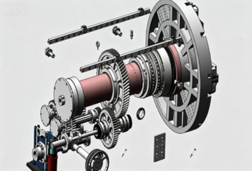
Matching torque to the workpiece
The torque a cut demands follows from the cutting force and the radius at which it acts. Cutting force grows with the chip cross-section — depth of cut multiplied by feed — and with the specific cutting force of the material. Because torque is that force multiplied by the workpiece radius, the same depth of cut on a large diameter demands proportionally more torque, even at the same surface speed. This is the most common source of disappointment in spindle selection: a machine chosen for its maximum swing, then found short of torque exactly where its size is being used.
Two other effects push the requirement up. Interrupted cuts — a casting skin, or a keyway crossing the tool — produce repeated force peaks rather than a steady load, and a spindle selected with no margin shows it as a speed dip. And roughing hard or work-hardening material raises the specific cutting force further.
Size it against the worst operation in your process rather than the average one, and state that operation explicitly: material and hardness, the diameter at which the heaviest cut is taken, the depth of cut and feed expected, and whether the cut is interrupted.
Where the requirement exceeds what a single-range spindle can deliver, the answer is normally a two-range arrangement rather than a bigger motor. Mechanical gearing multiplies torque at low speed, which is precisely the region where the curve falls short, and it does so without increasing the drive rating, the cabinet size or the electrical supply. The trade is a lower maximum speed and one more mechanical assembly in the drive train. The architecture options and their trade-offs are set out in the lathe series configurations, which show how the spindle arrangement changes across model sizes.
Matching speed to the material
Cutting speed is usually given as a surface speed in metres per minute, and the rpm needed to achieve it depends on the diameter being machined: the rpm is a thousand times the surface speed divided by pi times the diameter in millimetres. On a two-hundred metre per minute surface speed, a four-hundred millimetre diameter needs roughly one hundred and sixty rpm, while a forty millimetre bar needs roughly sixteen hundred. The diameter decides the speed band, and the material decides where inside it the tool is comfortable.
That relationship is why the workpiece family, not the machine size, drives the decision. Bar work lives at the top of the speed range and rewards a spindle built for it; large heavy work lives at the bottom, where torque is the constraint and top speed is irrelevant.
There is also a safety dimension that belongs in the selection rather than in the operator’s judgement. Chuck clamping force falls as speed rises, because centrifugal force acts on the jaws, so the safe speed for a given chuck and jaw set is limited by the gripping arrangement as well as by the spindle.
Bearings, lubrication and what limits the curve
The curve is delivered by the bearings as much as by the drive, which is why the bearing arrangement belongs in cnc spindle selection rather than in the maintenance file. Three arrangements appear in machine tool spindles, and each sets a different ceiling on speed, stiffness and life.
Angular contact bearings are arranged in pairs or sets and carry both radial and thrust loads, which is why they dominate the front position on turning spindles; a matched pair with a preload gives the rigidity that turning forces need. Cylindrical roller bearings carry much higher radial load for their size and give excellent radial stiffness, but they take little thrust on their own, so they are used where the thrust is handled elsewhere. For the highest speeds, hybrid bearings with ceramic rolling elements reduce mass and heat generation and allow higher speeds for the same bore. The engineering behind those families is documented by the bearing manufacturers, for example in SKF’s rolling bearing information, which is a reasonable reference when comparing what a quotation is claiming.
Lubrication sets the next limit. Grease is simple, sealed and effectively maintenance-free for a long period, and suits moderate speeds. Oil-air lubrication meters small, precise quantities of oil to each bearing and removes more heat, allowing higher speeds at the cost of a system to maintain. That is why two spindles of the same size have different speed ceilings.
The last element is how the shaft is allowed to grow. Heat expands the spindle shaft, and a bearing arrangement that constrains both ends will convert that expansion into preload and heat, which then increases further. A front arrangement that locates the shaft with a rear end that floats absorbs the growth instead. That design choice is invisible from the outside and shows up in how the machine behaves after an hour of running — precisely the condition an acceptance test should cover.
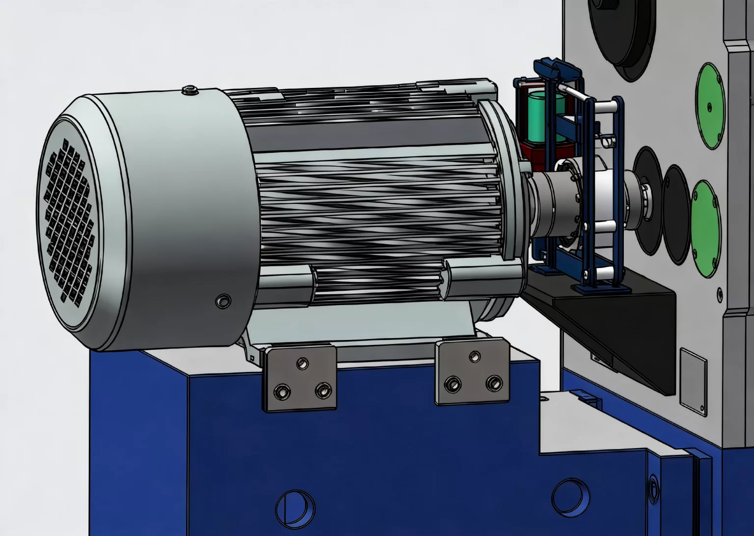
Thermal behaviour and the accuracy you keep
Every spindle produces heat, and heat moves the position of the tool relative to the workpiece. The sources are the bearings, the motor, the cutting process and the units around the headstock. Their effect is slow rather than dramatic, which is why acceptance tests specify whether measurements are taken from a cold start, after a warm-up, or both.
A well designed spindle manages this in three ways: heat is removed close to where it is generated, through a cooling jacket or an oil chiller; the bearing arrangement is allowed to grow in a controlled direction; and the machine has a warm-up routine, so the operator can reach working temperature before holding a tolerance on a precision part.
The practical consequence for cnc spindle selection is that a higher speed ceiling is not automatically better: more speed means more heat, so ask how the heat is removed and whether tolerance must hold from a cold start or after warm-up.
How to specify a spindle in the enquiry
CNC spindle selection is one of the few parts of a machine purchase where a single page of data from the buyer makes a large difference to the answer. Send the process; ask for the curve.
| What to send | The workpiece drawing for the heaviest operation, material and hardness, the diameter at which that cut is taken, the depth of cut and feed, and whether the cut is interrupted |
|---|---|
| Speed requirement | The surface speed you want to run, or the tool life you are trying to achieve, and the diameter band the work falls in — for example bar work from eight to forty millimetres |
| Accuracy requirement | The tolerance and surface finish you must hold, and whether it has to be held from a cold start or after warm-up |
| Workholding | Chuck or collet type, jaw arrangement, bar capacity, and whether a steady rest or tailstock is used with the spindle running at speed |
| Ask for the curve | The torque-speed curve of the proposed spindle, the base speed where constant torque ends, the bearing arrangement and lubrication method, and the cooling arrangement |
| Ask for the interface | Spindle nose or taper, bore, tool or chuck mounting standard, and whether the spindle supports a C-axis or indexing function for the process |
Data to have ready before the enquiry
- The heaviest cut in the process, with material, diameter, depth of cut and feed
- The speed band the work actually runs in, derived from the diameter and the surface speed
- The tolerance and surface finish that must be held, and under what thermal condition
- The workholding arrangement and the bar capacity required
What to compare between offers
- Torque at the operating speed, not the rated torque at an unspecified speed
- Base speed, and how much of your speed band falls in the constant-torque region
- Bearing arrangement, lubrication method and the maintenance it implies
- Cooling arrangement, warm-up requirement and the thermal condition of the acceptance test
Want the numbers rather than the adjectives? The machining centre range sets out the spindle and axis configurations available across the series, which is the fastest way to see whether the architecture you need already exists before the requirement is engineered. Where the spindle choice changes the price, the drivers behind it are explained in what determines CNC lathe price; where it changes the offer, in how to read a machine tool quotation.
Frequently asked questions
Should I choose the spindle with the highest power?
Not unless the workpiece deserves it. Power sets the ceiling on how fast material can be removed at speed; torque sets how much can be removed per revolution, which is the constraint on large diameters and heavy roughing. A higher power spindle with a narrow constant-torque region can be a worse choice for a large casting than a lower power spindle with a wide one. Compare torque at the speed you will run at, and read the base speed where the constant-torque region ends.
How do I know whether I need a two-range spindle?
By looking at the heaviest cut in the process rather than the machine size. If that cut is on a large diameter, involves material that resists machining, or is interrupted — a casting skin, a keyway, an intermittent surface — the low-speed torque requirement rises quickly, and the constant-torque region of a single-range spindle may not cover it. Two mechanical ranges trade top speed for torque at low speed, which is usually the right exchange when the work is heavy and the process will never use the highest rpm.
Does a higher maximum speed mean a better spindle?
It means a spindle designed for higher speed, which involves hybrid or ceramic bearings, oil-air lubrication and more attention to heat removal. That is exactly right for small-diameter work where the surface speed demands high rpm, and it is unnecessary for large-diameter work that cannot reach those speeds with a safe chuck. Higher speed also means more heat and more sensitive thermal behaviour, so the choice should follow the diameter band of the work rather than the number on the datasheet.
What is the warm-up routine for, and is it optional?
It brings the spindle and the headstock to their working temperature before a tolerance is held, so the first part of the day is not measured against a different thermal state from the last. It is not optional on a machine used for precision work: the geometry and the relative position of spindle, turret and tailstock all move slightly with temperature. Treat it as part of the specification, ask for the routine in the manual, and make sure the acceptance test states whether readings are taken cold, warm, or both.
Can the spindle be changed or upgraded later?
In practice, rarely, and never cheaply. The spindle is designed with the headstock, the bearings, the drive, the lubrication and the cooling around it, and its nose determines which chucks and tooling interface with it. That is why cnc spindle selection belongs at the requirement stage, alongside the workpiece and the workholding, rather than at the negotiation stage. A spindle that suits the process from the start avoids a decision that has no economical reversal later.
Next step
Send the heavy cut, and get the curve back. Send the workpiece, the material, the diameter and depth of cut of the operation that works the machine hardest, and our engineering team will return the spindle arrangement proposed for it, the torque-speed curve with its base speed marked, the bearing and lubrication arrangement, and the cooling requirement — so cnc spindle selection is made against a curve rather than against a kilowatt figure.
Request the spindle torque curve
WhatsApp: +86 15502628547 · Email: info@dhlathe.com
Attach the drawing for the heaviest operation and the tolerance you must hold. If the spindle needs a two-range arrangement, the proposal will say so and show what it does to the speed range.
