
Operation & Maintenance
CNC alarm codes are not a universal language. Each control builder numbers its own alarms, the same number can mean different things on two different controls, and the useful information is usually in the alarm text rather than in the number. What does generalise is the family an alarm belongs to: servo and axis, spindle, overtravel and reference, lubrication and coolant, hydraulic and pneumatic, door and interlock, program and operation, cabinet thermal, and system or communication faults. Reading which family an alarm belongs to, and in what order the alarms appeared, is what turns a screen full of text into a diagnosis.
Why the number tells you less than the text
There is no international register of cnc alarm codes. A control builder numbers its own alarms, then the machine builder adds the alarms generated by its own logic — the chuck clamp confirmation, the tool changer sequence, the lubrication cycle — and the drive manufacturer adds a third set with its own numbering behind the control’s display. The same three-digit number can therefore mean a following error on one machine and a lubrication fault on another.
What this means in practice is that a search for the bare number is often wasted effort, while the alarm text plus the machine model is almost always enough to identify the fault family. The text names the subsystem; the number only identifies the message inside that control’s own list. So the first thing to write down when an alarm appears is the full text, exactly as displayed, followed by the number.
The second thing to understand is that alarms come in kinds. A message that warns and lets the cycle finish is not the same as an alarm that stops the machine, and a hard alarm that has to be cleared deliberately is not the same as one that clears itself. The distinction decides whether the right response is to finish the part and investigate afterwards, or to stop immediately — and getting it wrong is how a correctable fault becomes a damaged machine.
The alarm families and what each one points to
Almost every cnc alarm code falls into one of nine families, and reading cnc alarm codes is largely a matter of identifying the family before hunting for the cause. The family narrows the search from hundreds of possibilities to a handful of checks.
| Family | What it usually indicates | Where to start |
|---|---|---|
| Servo and axis | Position deviation, overcurrent, overheat, feedback fault, drive not ready | Mechanical binding, way lubrication, contamination under a way cover, brake release, feedback connector |
| Spindle | Drive fault, speed deviation, orientation failure, spindle thermal, tool clamp not confirmed | Spindle load history, cooling and lubrication, clamp sensors, then the drive’s own alarm detail |
| Overtravel and reference | Soft limit exceeded, hard limit switch tripped, reference return not completed | Jogging clear in the safe direction, condition of the limit switch, and the manual’s reference procedure |
| Lubrication and coolant | Low lubrication level, lubrication cycle or pressure fault, coolant level or flow | Reservoir, pump, metering units and lines, the level switch, and the coolant return screen |
| Hydraulic and pneumatic | Pressure low or high, chuck clamp confirmation missing, tailstock or quill fault | Supply pressure, visible leaks, solenoid valve operation, pressure switches and clamp sensors |
| Door, guard and interlock | Safety circuit open, guard not closed, emergency stop not released | The guard, the interlock, and the emergency stop chain — never the interlock’s wiring as a workaround |
| Program and operation | Tool offset out of range, tool breakage detected, program syntax, wrong tool, reference not established | The program block being executed, the offsets, and the tool data — operator-level checks first |
| Cabinet thermal and electrical | Cabinet overheat, fan or cooler fault, drive overload, transformer temperature | Cabinet fan filters and cooler, ambient temperature, and the load the drive was carrying |
| System, memory and communication | Backup battery low, memory or parameter fault, bus error, communication loss between control and drive | Battery and parameter backup status, then connectors and cabling — and stop before clearing anything |
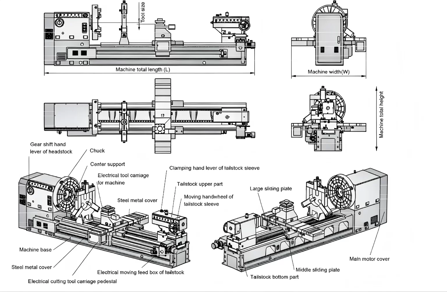
Servo, spindle and overtravel alarms
Servo alarms describe an axis that could not go where it was told or could not hold where it was. The measurable symptom is position deviation: the control asked for a position, the feedback device reported a different one, and the two diverged beyond a limit. Three causes account for most of them, and they are worth checking in this order. A mechanical restriction — contaminated guideways, a way cover that has collected swarf, a seized bearing, an axis brake that has not released — is the most common. A lubrication fault on that axis is the second, and it is the reason lubrication alarms should never be treated as minor. The third is the feedback chain itself: an encoder coupling, a connector, or a cable damaged by chips or coolant.
Spindle alarms follow the same logic applied to rotation. A speed deviation means the spindle did not reach or hold the commanded speed; a drive fault usually carries its own detail behind the control display, in the drive’s parameter or diagnostic screen, and that detail is the most useful piece of information on the machine when the alarm appears. An orientation failure usually points at the spindle position encoder or the mechanical relationship between the spindle and the tool change. A thermal alarm is the one to take seriously rather than clear: it means something in the bearing, lubrication or cooling arrangement has changed.
Overtravel and reference alarms are the family where good intentions cause the most damage. A soft limit alarm means the programmed position was outside the permitted travel and is resolved by returning the axis inside the limit. A hard limit switch means the axis reached the physical switch, and the correct response is to jog clear in the safe direction at reduced feed — never to force the axis against the stop. A reference alarm means the machine has lost its relationship between the mechanical position and the control’s coordinate system. Re-establishing it is a procedure from the manual, and on machines with absolute encoders it is not something to be improvised: resetting a reference incorrectly can leave the control believing the machine is somewhere it is not, which is how a collision begins.
Lubrication, coolant, hydraulic and pneumatic alarms
This family of alarms is the most easily dismissed and the most worth acting on immediately. A lubrication alarm — low level, no pressure, or a cycle that did not complete within its expected time — is the machine telling you that a guideway, a ball screw or a spindle bearing is about to run dry. The correct response is to stop and find out why, because the alternatives are a blocked metering unit, a failed pump, a broken line or a level sensor that has failed, and three of those four do real damage within a shift.
Coolant alarms are usually level or flow, and the underlying causes are mostly housekeeping: a return screen clogged with fines, a pump inlet blocked, a concentration that has drifted, or a float switch stuck by swarf. They are worth fixing properly rather than bypassing, because coolant starvation shows up first as tool wear and then as a surface finish problem that takes a long time to attribute correctly.
Hydraulic and pneumatic alarms point at two systems that are mechanically simple and diagnostically straightforward: pressure low, pressure high, or a confirmation signal that did not arrive. A missing chuck clamp confirmation, for example, is either a genuine clamping problem, a pressure drop, or a sensor that has failed — and the safe assumption is always the first until it is proved otherwise. These faults also interact with the machine’s safety logic, which is why they tend to stop the cycle rather than warn.
Safety, cabinet and system alarms
Door, guard and interlock alarms mean the safety circuit is open. The response is to find out which element is open — the guard, the interlock, the emergency stop chain — and to close it properly. This is the one family where a workaround is never acceptable: bridging an interlock to finish a batch removes the only protection between an operator and a rotating workpiece, and it converts a maintenance task into an incident. The general expectation that work equipment is maintained in a safe condition is set out in the guidance on the maintenance of work equipment, and interlocks are part of that condition rather than an obstacle to production.
Cabinet thermal and electrical alarms are the slow ones. Cabinet overheat, a fan or cooler fault and drive overload usually mean a filter that has not been cleaned, an ambient temperature that has risen, or a drive working harder than it used to. They rarely stop production immediately and are therefore the most commonly ignored — and the most reliable predictor of an electronics failure a few months later.
System, memory and communication alarms sit at the other end of the scale. A low backup battery is a three-minute task that becomes an expensive one if ignored, because the memory it protects holds the parameters and the offset data. A bus or communication error between the control and a drive is worth investigating before anything is cleared: the same message can come from a loose connector or from a failing board.
How to read an alarm properly
Reading cnc alarm codes is a method, and the method is the same whether the machine is young or old. Work through it in order; the first two steps are what make the rest possible.
First, capture
- Photograph the screen with the alarm text and the number exactly as displayed
- Note what the machine was doing: the program block, the axis movement, the tool change, the spindle speed
- Check the alarm history and write down the order — on most machines the first alarm is the cause and the following ones are consequences
- Note whether it is repeatable, intermittent, or has appeared for the first time, and whether anything changed recently on the machine
Then, diagnose in this order
- Secure the machine: spindle stopped, axes clear, no part in a position that could move under gravity
- Clear the simple physical causes: guard and interlock, air pressure, chuck clamp confirmation, lubrication level, coolant level, cabinet fans
- Read the detail behind the message — the drive’s own diagnostic display usually carries the specific fault
- Isolate in manual at reduced feed: single axis, no load, handwheel, one movement at a time
- If it needs escalation, send the captured record rather than a description of the symptom
What makes a fault report useful
The difference between a fault resolved in one exchange and one that takes a week of messages is almost always in what was recorded before the machine was touched. Keep it in the same file as the maintenance record described in the daily and weekly maintenance checklist, because the two are read together.
| Machine identification | Model, machine number and the hours or year of operation, plus the control and drive model |
|---|---|
| The alarm itself | The full text and the number, and a photograph of the screen if the message is long |
| The alarm history | Which alarms came first, in order, and how long the machine ran between them |
| What the machine was doing | The program block, the axis and direction, the spindle speed and feed, the tool in use, and whether it was the first part of the shift |
| Conditions and timing | Cold or warm machine, how it behaves on a restart, whether it happens once a shift or once a minute |
| What changed | Any recent maintenance, parameter change, tooling change, new program, new material, or change in the environment |
| What has been tried | What was cleared, what was reset, what was measured — with the result of each attempt |
| Readings | Supply pressure, lubrication consumption, hydraulic temperature, drive load if available, and any indicator reading taken |
What not to do when an alarm appears
Do
- Record the text, the history and the machine’s condition before clearing anything
- Clear once to see whether the condition is repeatable, then stop and diagnose
- Treat lubrication, coolant and thermal alarms as early warnings rather than nuisances
- Keep a current parameter backup and a copy of the machine manual’s alarm list with the machine
Do not
- Clear the same alarm repeatedly and keep running — that is how a drive becomes a replacement
- Bridge or bypass an interlock, a guard switch or an emergency stop circuit, for any reason
- Swap drives or boards, or restore parameters, before a backup has been taken
- Reset an absolute encoder reference or adjust a limit parameter to make the message disappear
None of this requires an engineer on site. Most cnc alarm codes resolve into a handful of physical causes, and the discipline that finds them is the same one that keeps a machine running: capture the evidence, identify the family, check the simple things first, and change nothing that cannot be undone.
Frequently asked questions
What do cnc alarm codes actually mean?
Each control builder defines its own set, and the machine builder adds its own logic on top, so the number is only meaningful against that machine’s alarm list. The text is what identifies the subsystem, and the number identifies the specific message within that control. That is why the manual’s alarm list is the authority rather than a general table: two machines with the same control can show the same number for different faults if the machine builders have generated their own messages in that range.
Why does the same alarm appear only sometimes?
Intermittent alarms almost always have a condition attached: temperature, load, or position along an axis. A servo alarm that appears after an hour of running points at thermal growth, lubrication or a binding that only shows when the machine is warm. One that appears at the same point in the travel points at a section of guideway, a way cover, or a cable that flexes there. One that appears under heavy cutting but not in air points at load. Writing down the conditions each time turns an intermittent fault into a pattern, and the pattern usually names the cause.
Is it safe to clear an alarm and continue?
Once, to establish whether the condition repeats, yes. Repeatedly, no. Some alarms indicate a condition that has already been corrected and are cleared for that reason; others are latching and describe a fault that will return, usually with more damage, if the machine is restarted each time. Safety-related alarms are a separate category and should never be cleared as a way of continuing production — clearing an interlock alarm without finding which element is open removes a protection rather than a nuisance.
Where do I find the meaning of a specific alarm?
Three places, in order of authority: the machine manual’s alarm list, which covers both the control messages and the machine-specific ones; the control’s own alarm or diagnostic display, which usually carries more detail than the summary line; and the drive manufacturer’s diagnostic parameters, which describe the specific fault behind a generic drive alarm. Keep the printed alarm list and the parameter backup with the machine rather than in an office drawer: cnc alarm codes are not something to look up from memory with the machine stopped and a shift waiting.
When should an alarm be escalated to the machine builder?
When the alarm is repeatable and the causes in its family have been checked, or when it involves a drive, the control, a reference or a parameter that should not be changed without instruction. Send the record rather than the symptom: machine model and number, the exact alarm text and number, the alarm history, what the machine was doing, what has been tried, and the readings taken. That record is what allows an answer to be specific instead of a list of possibilities.
Next step
Send the alarm, not a description of the problem. Send the machine model and number, the exact alarm text and number, the alarm history, what the machine was doing when it appeared and what has already been tried, and our engineering team will come back with the diagnostic order for that alarm — the checks to make in sequence on that specific machine, and the parts or settings that should be verified before anything is replaced. Installation-related faults that appear on a machine just put into service are covered in the commissioning checklist, and leveling and geometry symptoms in the alignment procedure.
Send an alarm record for diagnosis
WhatsApp: +86 15502628547 · Email: info@dhlathe.com
A photograph of the screen is the most useful single attachment. Add the control and drive model from the machine’s configuration pages so the alarm list can be matched exactly.
